How to prepare your architecture design for wind and microclimate simulations.
In a nutshell…
Just follow these steps:
- Simplify your geometry to roughly 0.5 meters
- Make buildings watertight
- Check mesh quality (e.g. double vertices)
- Export buildings (+ optionally terrain and trees)
Done. There is nothing more to it. Send us the files and we’ll do the rest.
Simply use your usual, favorite 3D design software - there is no need for licenses, additional proprietary software, training courses, etc. In fact, if you would prefer us to prepare the model for you, just let us know!
Depending on the type of simulation (e.g. microclimate), you will receive your results between one and five days after submission in most cases. In addition to your report, we are happy to provide 3D-results, either in our in-house viewer or for importing into your design software.
Find more detailed information below, such as supported file types, terrain and trees. There is also our handy geometry preparation guide as pdf to download for your convenience.

What to provide
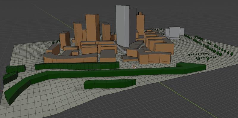
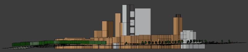
We distinguish between three different basic mesh layers for most simulations for the build environment / architecture:
- Buildings: containing all buildings existing or planned
- Terrain: the actual or planned terrain of your project
- Trees: all leafy plants from single trees to contiguous bushes
These three categories are typically handled as three different files in one of the listed file formats (see below), sharing a common origin.
For all of these files, keep the mesh as low-poly as you can, with a level-of-detail (LOD) in the range of decimeters (0.2m - 1.0m, with 0.5m usually offering the best trade-off).
Make sure to avoid the following:
- double vertices / edges / faces - any features that share the same or almost the same space in the virtual geometry
- edges / faces that intersect without a point / edge at the intersection - whenever an edge / face intersects something, the intersection needs to be a point or edge
- unconnected vertices / edges / faces - unconnected vertices, edges that are not connected to faces, and faces that do not form a 3-dimensional structure are not permitted
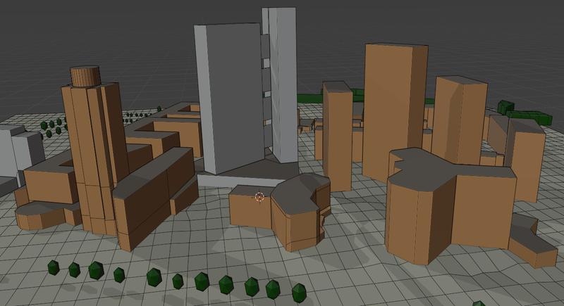
Buildings
Our simulations only ever work on the outer shell of a building, interior features are not necessary and might cause errors. All buildings must be “watertight” 3-dimensional objects. Ideally, the outer building shell is a single surface without any “unintentional” gaps. For example, there should not be gaps for doors, windows, or between the body of the building and the roof.
In more technical terms: all buildings should be 2-manifold meshes without boundary edges. That means: no self-intersection, every edge starting from a vertex leads to a full triangle loop, and every edge is attached to exactly 2 triangles.
It is, however, absolutely fine to have intentional openings in a structure, like for example an open terrace-level in a high-rise building. But in this case, too, the building itself must be a “watertight” body.
The shape of buildings is not restricted in any way. Your are free to use curved structures, openings, pillars, bridges, thoroughfares, etc.
Thin structures, such as walls or awnings, must also be 3-dimensional bodies and cannot be comprised of a single face with a front- and backside.
For buildings that continue into the terrain (see below), their floor can be left open, so that the intersection of terrain and building forms a watertight body.
The building layer should contain your planned building and can include existing buildings / structures surrounding your project if you want to include their influence. This might - for example - be important if a high-rise building exists in vicinity of your planned project. For a fee, we can include existing structures from OSM-data (Open Street Map), if these kind of data are available and of sufficient quality.

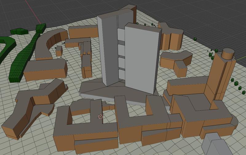
Terrain
As an exemption and different to buildings, the terrain should be a single surface mesh, and not a 3-dimensional body. It should only consist of faces with a front- and backside.
Any structures that penetrate into the terrain will automatically intersect with the terrain for the simulation. It is not necessary to perform this intersection before. Usually, the best approach is to simply extrude your building downwards a couple of meters so that all walls completely intersect with the terrain.
Obviously, the terrain should ideally include any earth movement that is planned. If no terrain is available for your location or particular planning stage, we can provide terrain data from satellite digital elevation maps for a fee. In that case, please make sure to include exact coordinates and ideally a map (geolocated or at least including landmarks), so that we can place your buildings correctly on the terrain. Also make sure that you let us know at which height your buildings will intersect with the terrain (e.g. highest point of roof of building x is y meters above ground).


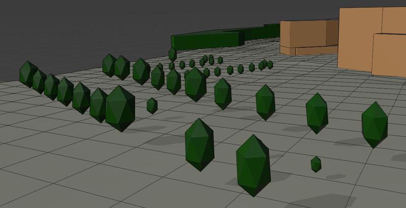
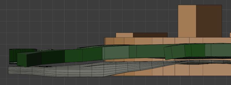
Trees
Similar to buildings, trees are represented as 3-dimensional structures. These can either be single trees or larger, forested areas. Trunks should not be included.
Unlike buildings, tree structures have less strict requirements for being “watertight”, as they are simulated as areas that can be penetrated by air and slow down its velocity. While wind is not penetrating building envelopes, it can and should flow through foliage of bushes and trees. In our simulations, the wind will gradually slow down in these areas, carefully calibrated just like in the real world, where wind does not penetrate much more than 50 meters into forests. Obviously, trees usually do not intersect with the terrain, though it is fine if they do, e.g. for bushes and hedges.
The tree layer may be omitted completely.

File Formats
The three mesh layers, buildings, terrain and trees, can be submitted in the following file formats (each layer in a separate file):
- ifc - Industry Foundation Classes - an open, industrial BIM format, backed by ISO standards (a very robust option)
- obj - Wavefront OBJ File Format - an open geometry format
- stl - the stereolitography file format - widely used for describing surfaces
- iges - Initial Graphics Exchange Specification - an older but versatile and vendor-independent file format
- blend - the open-source blender file format
If your CAD software can export into any of these (most support at least obj and stl), we can work with your model out of the box, as long as you follow the guidelines above. Being able to work with your exported model straight away ensures that we can deliver results fast and with 100% fidelity. In cases where we need to change something - the most frequent things are closing open faces and adding volume (thickness) to faces - we will let you know.

Published: