Dynamic Simulation of a Wind Turbine

Unsteady CFD simulations of wind turbines yield detailed insights into the structure, size and power of trailing vortices. Those down-stream eddies, combined with strongly decelerated flow within the direct slipstream, effect efficiency of wind turbines far downstream. Parameters such as wind-speed, the shape of the wind-profile, airfoil pitch, landscape peculiarities, etc. are included in physically correct models. From the simulation results, design criteria like positions and placement patterns of highly efficient wind parks can already be obtained in the planning phase.
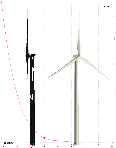
As an example, consider the simulation of a typical wind-turbine with a nominal power of 2.3MW. The applied wind profile and the simulated geometry are shown in the image on the right.
Parameters of the simulated wind turbine:
Rotor height: 78m
Rotor diameter: 80m
Exponential wind profile, Turbulent intensity: 5%
Wind speed at rotor height: 15.3 m/s
Tip speed ratio: 6
Air foil pitch: 10°

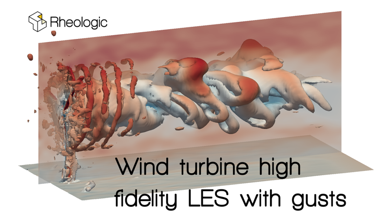
Using the approach explained above, we ran a transient simulation of the turbine and visualized the vorticity caused by the rotation of the blades (see video below). The vorticity is highest where the blades of the turbine move fastest: at their tips. Apart from the turbulence, you can also see that there is a distinct vertical difference in wind speed causing a distortion of the “turbulence helix”. Also visible (indicated by the blue color in the rendering) is the downwind loss of fluid velocity over the cross section of the rotor - the rotor harvests impulse from the moving air.
In this video, we used a high-fidelity LES approach. In our experience, this routinely achieves results of consistently higher quality compared to other, less involved simulation approaches. Additionally, we included generated turbulence at the inlet (incoming “blobs”) to demonstrate that this kind of simulation can also be done with gusts.
Gusts can also be generated on top of arbitrary vertical velocity profiles. Especially for onshore turbines, we do use a number of precursor simulations to determine this inlet profile. For example: turbines are often located on top of hills / ridges. However, in such situations, the wind rarely approaches horizontally, but has a distinct upwards component that can drastically change the load on blades, tower and transmission. Therefore, using a progression from coarse meteorological simulation as input for a better resolved RANS, which in turn is the input for a LES, gives a much better impression of the real flow condition around the turbine. If this information is factored into the planning process, tailored engineering of the turbine can be conducted for its specific location.
Let’s compare the above to the simpler approach of a k-epsilon simulation without generated turbulence at the inlet, as shown in the video below. While the overall picture is similar to the LES, there are significant differences in the turbulence around the blades, with the LES showing a picture much closer to reality.
Reality Check
In a large scale PIV (particle image velocimetry) experiment at the University of Minnesota, all these phenomena were demonstrated using an industrial scale wind turbine. Details about this can be found in this paper titled “Natural snowfall reveals large-scale flow structures in the wake of a 2.5-MW wind turbine” published in Nature. A nice video about the experiment, showing the vortices, can be found on the University of Minnesota’s dedicated website: Super-Large-Scale Flow Visualizations. Compare the video of the actual phenomenon to the slow motion animation of our simulation (see below). Even though the conditions of the experiment and the simulation were not synchronized (we only became aware of the experiment after completing our simulation), qualitatively, the resulting images look remarkably similar.
If you have a specific situation at hand, and need a detailed assessment on the forces that work on your turbine (for example on exposed cliffs, in hilly terrain or somewhere with a high density of turbines), contact us! We are happy to take a look. The first consultation is always free!
Published:
